GPS Support - Tracking System Alerts
Our Tracking System GPS Alerts are triggered when a vehicle violates a pre-set parameter, such as overspeed or crossing a Geofence boundary, for example. An automatic email is sent, with details such as date, time, location for a situation which merits attention.
Email alerts can be sent to your Blackberry or portable device. You can monitor your company while out of the office or away from your desk.
GPS Support - GPS AnyPlace
Tracking System GPS AnyPlaceTechnical Support and Instructions. If you need further assistance please call Gary at (313) 402 0700, or for IT support please contact Robin on (813) 419 4382
- GPS Tracking Device Installation
- Panic Button
- Alert Setup
- Relay Wiring
- Wiring Harness
GPS Fleet Tracking Support and Instructions
A clear view of the sky is important for the location of the GPS antenna. It MUST be placed in an open space not obscured by metal.
GPS Installation Diagram
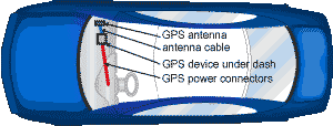
Step One
Determine a location for the GPS device. We recommend installation behind the glove box under the dash. This location allows the antenna to “look” up through the windshield for its signal. Much of this space will likely be used by the passenger airbag but usually there is enough available space somewhere in this area to mount the device.
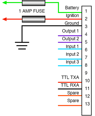
Once you have installed the device, plug the data port attached to one end of the cable into the unit. For powering the GPS unit we suggest connecting the wires at the other end of the cable to the vehicle fuse panel. For the green or white wire labelled gnition, look for a source that will go OFF/ON with the key. For the red wire labelled battery, look for a source that is always “HOT”.
Important:
Ensure that this source does not go OFF/ON when the Ignition is switched OFF/ON.
Determine the fuse used in your vehicle and connect these 2 wires using the supplied connectors. For the black wire labelled ground, find a source that is chassis grounded. You may need to drill mount your own screw for this connection.
Note:
To provide a secure connection and to avoid severing or pinching these fine wires, we suggest stripping about 1" and folding the wire twice before inserting into and crimping the connector. Use the cable ties (supplied) to secure the cable.


STEP TWO
Place the GPS/cellular antenna (side with the receiver facing up) beneath the dash. The antenna must be as horizontal as possible, but in no case greater than 20 degrees from horizontal. Never place the antenna under metal; your unit will not work. If there is no room under the front dash, you might try the rear deck of an automobile with a rear window.
Once the antenna is mounted, connect the wires as labelled:
One to the GPS connector with a yellow band that says GPS, and the other to the cellular connector. Ensure they are connected very secure and screwed on securely but DO NOT over tighten.
To verify your unit is functioning, the LED labelled PWR should be lit red. When the ignition is turned on, the ignition IGN LED should light yellow, and the green GPS light will be on for 5 seconds then off for 5 seconds. Once the device has GPS location data, the LED will be on for 2 seconds then off for 2 seconds.Your unit is working properly.
Place electrical tape over the LED if you wish to hide the lights. Dress your wires and put the vehicle back together.
It is recommended that you now test the unit via the GPS AnyPlace website using your personal username and secret password.
If you have any difficulties please call Gary Ryan at (313) 402-0700.
Our Panic Button is a one-push emergency button which sends an instant alert which sends you a danger warning and the location of the vehicle via text message or email. It can also be set up to notify 911 emergency centers in case of emergency situations.
Panic Button Text Messaging Setup
This table outlines setting up text messaging to reflect emergency or other events that occur in the vehicle equipped with a GPS AnyPlace device, so it will send a text message or email to one or more recipients. e.g. if your phone number is (989)555-2900 and your mobile provider is TMobile send an e-mail to 9895552900@tmomail.net.
| Data Carrier | Device | Email Address |
| AllTel | none | 10digitphonenumber@message.alltel.com |
| Ameritech/SBC Paging | 1 way | 10digitphonenumber@paging.acswireless.com |
| Ameritech/SBC Paging | 2 way | 10digitphonenumber@airmessage.net |
| Arch | 1 way | 10digitphonenumber@archwireless.com7 |
| Arch | 2 way | 10digitPIN@archwireless.net |
| AT&T Wireless | Blackberry/SMS | 10digitphonenumber@mobile.att.net |
| Cingular Wireless | Blackberry/SMS | 10digitnumber@mobile.mycingular.net |
| Metrocall | 1 way | 10digitphonenumber@page.metrocall.com |
| Metrocall | 2 way | 10digitphonenumber@My2Way.com |
| Motient | 2 way | username@2way.net |
| Nextel | Phone | 10digitphonenumber@messaging.nextel.com |
| Qwest | none | 10digitphonenumber@qwestmp.com |
| SkyTel | 1 way/2 way | 7digitPIN@skytel.com |
| Sprint PCS | Phone | 10digitphonenumber@messaging.sprintpcs.com |
| TMobile | none | 10digitphonenumber@tmomail.net |
| Verizon Wireless Cellular | none | 10digitphonenumber@vtext.com |
| Verizon Wireless Cellular | 1 way | 10digitphonenumber@pager.myairmail.com |
| Verizon Wireless Messaging | 2 way | 10digitphonenumber@myairmail.com |
| WebLink Wireless | 1 way | 7digitPIN@pagemart.net |
| WebLink Wireless | 1.5 way/2 way | 10digitphonenumber@airmessage.net |
Free Email To SMS Gateways (Major US Carriers)
| Carrier | Email to SMS Gateway |
| AllTel | 10digitphonenumber@message.alltel.com |
| AT&T (formerly Cingular) | 10digitphonenumber@txt.att.net 10digitphonenumber@txt.att.net (MMS) 10digitphonenumber@cingularme.com |
| Boost Mobile | 10digitphonenumber@myboostmobile.com |
| Nextel (now Sprint Nextel) | 10digitphonenumber@messaging.nextel.com |
| Sprint PCS (now Sprint Nextel) | 10digitphonenumber@messaging.sprintpcs.com 10digitphonenumber@pm.sprint.com (MMS) |
| T-Mobile | 10digitphonenumber@tmomail.net |
| US Cellular | 10digitnumber@email.uscc.net (SMS) 10digitnumber@mms.uscc.net (MMS) |
| Verizon | 10digitphonenumber@vtext.com 10digitphonenumber@vzwpix.com (MMS) |
| Virgin Mobile USA | 10digitphonenumber@vmobl.com |
| Motient | username@2way.net |
| Nextel | 10digitphonenumber@messaging.nextel.com |
| Qwest | 10digitphonenumber@qwestmp.com |
| SkyTel | 7digitPIN@skytel.com |
| Sprint PCS | 10digitphonenumber@messaging.sprintpcs.com |
| TMobile | 10digitphonenumber@tmomail.net |
| Verizon Wireless Cellular | 10digitphonenumber@vtext.com |
| Verizon Wireless Cellular | 10digitphonenumber@pager.myairmail.com |
| Verizon Wireless Messaging | 10digitphonenumber@myairmail.com |
| WebLink Wireless | 7digitPIN@pagemart.net |
| WebLink Wireless | 10digitphonenumber@airmessage.net |
Free Email To SMS Gateways (International + Smaller US)
| Carrier | Email to SMS Gateway |
| 7-11 Speakout (USA GSM) | number@cingularme.com |
| Airtel (Karnataka, India) | number@airtellkk.com |
| Airtel Wireless (Montana, USA) | number@sms.airtelmontana.com |
| Alaska Communications Systems | number@msg.acsalaska.com |
| Aql | number@text.aql.com |
| AT&T Enterprise Paging | number@page.att.net |
| BigRedGiant Mobile Solutions | number@tachyonsms.co.uk |
| Bell Mobility & Solo Mobile (Canada) | number@txt.bell.ca |
| BPL Mobile (Mumbai, India) | number@bplmobile.com |
| Cellular One (Dobson) | number@mobile.celloneusa.com |
| Cingular (Postpaid) | number@cingularme.com |
| Centennial Wireless | number@cwemail.com |
| Cingular (GoPhone prepaid) | number@cingularme.com (SMS) |
| Claro (Brasil) | number@clarotorpedo.com.br |
| Claro (Nicaragua) | number@ideasclaro-ca.com |
| Comcel | number@comcel.com.co |
| Cricket | number@sms.mycricket.com (SMS) |
| CTI | number@myairmail.com |
| Emtel (Mauritius) | number@emtelworld.net |
| Fido (Canada) | number@fido.ca |
| General Communications Inc. | number@msg.gci.net |
| Globalstar (satellite) | number@globalstarusa.com |
| Helio | number@messaging.sprintpcs.com |
| Illinois Valley Cellular | number@ivctext.com |
| Iridium (satellite) | number@msg.iridium.com |
| Iusacell | number@rek2.com.mx |
| i wireless | number.iws@iwspcs.net |
| Koodo Mobile (Canada) | number@msg.koodomobile.com |
| LMT (Latvia) | number@sms.lmt.lv |
| Meteor (Ireland) | number@sms.mymeteor.ie |
| Mero Mobile (Nepal) | 997number@sms.spicenepal.com |
| MetroPCS | number@mymetropcs.com |
| Moviecom (Argentina) | number@sms.movistar.net.ar |
| Mobitel (Sri Lanka) | number@sms.mobitel.lk |
| Movistar (Columbia) | number@movistar.com.co |
| MTN (South Africa) | number@sms.co.za |
| MTS (Canada) | number@text.mtsmobility.com |
| Nextel (United States) | number@messaging.nextel.com |
| Nextel (Argentina) | TwoWay.11number@nextel.net.ar |
| Orange Polska (Poland) | 9digitnumber@orange.pl |
| Personal (Argentina) | number@alertas.personal.com.ar |
| Plus GSM (Poland) | +48number@text.plusgsm.pl |
| President's Choice (Canada) | number@txt.bell.ca |
| Qwest | number@qwestmp.com |
| Rogers (Canada) | number@pcs.rogers.com |
| SL Interactive (Australia) | number@slinteractive.com.au |
| Sasktel (Canada) | number@sms.sasktel.com |
| Setar Mobile email (Aruba) | 297+number@mas.aw |
| Suncom | number@tms.suncom.com |
| T-Mobile (Austria) | number@sms.t-mobile.at |
| T-Mobile (UK) | number@t-mobile.uk.net |
| Telus Mobility (Canada) | number@msg.telus.com |
| Thumb Cellular | number@sms.thumbcellular.com |
| Tigo (formerly Ola) | number@sms.tigo.com.co |
| Tracfone (prepaid) | number@mmst5.tracfone.com |
| Unicel | number@utext.com |
| Virgin Mobile (Canada) | number@vmobile.ca |
| Vodacom (South Africa) | number@voda.co.za |
| Vodafone (Italy) | number@sms.vodafone.it |
| YCC | number@sms.ycc.ru |
| MobilePCS (Hawaii only) | number@mobipcs.net |
Step One
Connect black wire with two spade connectors to positions #86 and #30 on the Bosch relay. This wire then goes to a good ground point in the vehicle. Connect the yellow wire (with a pin connector on the end of it to push into the white wiring connector on the GPS unit) to position #87. This wire then connects to pin position #7 on the wiring harness white plastic piece. Be sure the pin inserts all the way and be careful not to bend or break it.
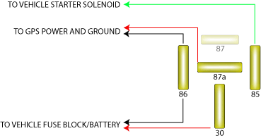
Step Two
Connect the red wire to relay position # 85. Connect other end of the red wire to the switch or device that powers up or is activated when the power supply causes the PTO or other device to work. This sends 12 volts to the relay causing it to close and send a grounded signal to the GPS device at pin position #7. That is the 7th hole from the right if looking at the wiring harness plugged into the GPS device.
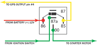
The relay is pre-wired for you. All you need to do is insert the pin on the yellow wire to the 4th pin position in the wiring harness on the GPS device. It would be the 4th position from the left. It is the pin slot next to the red, black and white wires already in the harness.

PIN # 4 |
INPUT # 1 INPUT # 2 INPUT # 3 OUTPUT # 1 OUTPUT # 2 BATTERY BACKUP LOOP BATTERY BACKUP LOOP |
